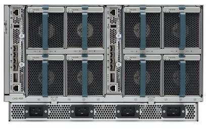
This may also apply to the UCS 5108 chassis in general, but as of writing this I haven’t had a chance to check one.
So here is the back of the chassis. And I figured common sense would say keep the two power ports on the right going to the right PDU, and the two ports on the left going to the left PDU… sounds logical right ?
Well it turns out that the power supplies are labeled 4, 3, 2, 1 … meaning the one on the left is PSU 4, and the one on the right is PSU 1. So when the chassis figures out that it doesnt need all 4 PSU’s online it will start putting PSU’s in power save mode from left to right. So PSU 4 is the first to go into power save mode, then PSU 3. (Note that by default with an N+1 redundancy policy there will always be at least two online)
If you have all 8 blades, or in my case 6 on this last install, powered up this isn’t such a big deal because the chassis lights up at least 3 of the 4 PSU’s. So if you cable the power like i mentioned before you have two feeds coming from PDU A and one from PDU B. HOWEVER if the chassis puts both PSU 4 and PSU 3 into power save mode you are effectively drawing power only from PDU A. But what if you lose PDU A???? Will the other two PSU’s come back online fast enough to prevent power loss to the chassis ?
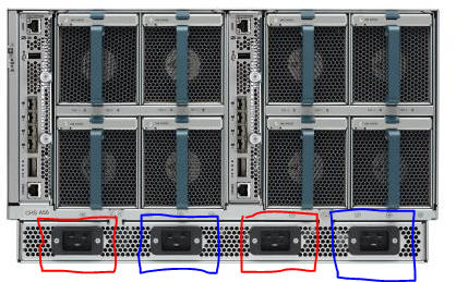
I wasn’t sure, so I went with the safe bet. I cabled the PSU’s circled in blue to PDU A and the ones in red to PDU B. this way there will always be at least one PSU on each PDU.
Next time I have some extra time to mess around I will do some real testing to see if the chassis goes offline during a PDU failure if cabled the first way.
Also, I guess that I should note that the reason this concerns me more on the mini than a normal 6200 series FI setup is because the FI’s are in the chassis. So if you lose power and those FI’s go offline you would probably be down for a decent amount of time while the FI’s boot back up and then the servers power on, and traffic forwarding resumes.
![]()


Yep, that is the same PS numbering scheme as with the “full” 5108.
With the mini that I just rolled out (3.0(1d)), I cabled 2-left and 2-right, and with three blades, it powered down PSU’s 3 and 1 (flashing green). When I flipped power policy into grid mode, they all came online and began outputting the same…
Tony Harvey (@tonyknowspower) from Cisco here. This is by design, the assumption with N+1 power is that you only need protection from a PSU failure not from a PDU failure. If you want protection from a PDU failure set it to Grid mode and all 4 PSU will come online and you will have full protection.
God to know Tony! Thanks for the info
In an N+1 configuration, where all 4 PSUs are connected, in what situation would the system put two PSUs into power save mode? Standard mode? If N=3, shouldn’t 3 out of the 4 be running all the time? And only one in standby.
If I Use Grid with Four PSUs for PDU Failure. How to connect PSU cable to the PDU ?
PSU 1,3 on PDU A and PSU 2,4 on PDU B , it’s the best solution?
I use Grid mode on my production deployments when I have A and B power drops.
page 33
http://www.cisco.com/c/en/us/td/docs/unified_computing/ucs/hw/chassis-install-guide/ucs5108_install.pdf
Grid Redundancy
The grid redundant configuration is sometimes used when you have two power sources to power a chassis or you require greater than N+1 redundancy. If one source fails (which causes a loss of power to one or two power supplies), the surviving power supplies on the other power circuit continue to provide power to the chassis. A common reason for using grid redundancy is if the rack power distribution is such that power is provided by two PDUs and you want the grid redundancy protection in the case of a PDU failure.
Pingback: Cisco UCS 5108 Chassis Power Policy Options and Redundancy – Real World UCS